数据链路层封装技术
现在98%的网络都是基于以太网实现的,之所以串行链路没有被完全淘汰,是因为它更安全,以太网中的信息传输容易被第三者截获,而串行链路中只能点到点进行通信,就保证了数据的安全。
其中点到点即在一个网络中,节点的数量被物理和逻辑地限制为2个,他是基于点到点类型工作的二层封装技术,不存在二层单播地址,比如MAC地址
串行链路的二层技术:PPP、HDLC、FR、X25、ATM,我们这里只讲PPP、HDLC,其余的基本快淘汰,甚至已经淘汰。
HDLC(High-Level Data Link Control,高级数据链路控制),是链路层协议的一项国际标准,每个厂商的HDLC技术均为私有技术,它是Cisco默认使用的封装技术

将这个网络中的链路层协议修改为HDLC:
1
2
3
4
5
6
7
8
9
10
|
[R1]interface s4/0/0
[R1-Serial4/0/0]link-protocol hdlc
Warning: The encapsulation protocol of the link will be changed. Continue? [Y/N]:y
Jul 18 2022 19:54:48-08:00 R1 %%01IFNET/4/CHANGE_ENCAP(l)[0]:The user performed the configuration that will change the encapsulation protocol of the link and then selected Y.
//R1
[R2]interface s4/0/0
[R2-Serial4/0/0]link-protocol hdlc
Warning: The encapsulation protocol of the link will be changed. Continue? [Y/N]:y
Jul 18 2022 19:55:35-08:00 R2 %%01IFNET/4/CHANGE_ENCAP(l)[0]:The user performed the configuration that will change the encapsulation protocol of the link and then selected Y.
|
可以查看该接口来查看使用的协议:display interface s4/0/0
ppp(Point-to-Point Protocol)点到点协议:它的网络类型是点到点网络类型,因此它没有二层地址,仅连接两个节点。
他是非Cisco串线接口默认使用的封装技术(公有)
在这种网络类型中,即便是不同网段的两点间也可以通信
PPP链路的建立有三个阶段的协商过程,链路层协商、认证协商(可选)和网络层协商
链路层协商:通过LCP报文进行链路参数协商,建立链路层连接
认证协商:通过链路建立阶段协商的认证方式进行链路认证(PAP、CHAP)
网络层协商:通过NCP协商来选择和配置一个网络层协议并进行网络层参数协商
a. PAP(密码验证协议)是明文传递用户名和密码
1
2
3
4
5
6
7
8
9
10
11
|
[R1]aaa
[R1-aaa]local-user huawei password cipher huawei123
Info: Add a new user.
[R1-aaa]local-user huawei service-type ppp
[R1-aaa]q
[R1]interface s4/0/0
[R1-Serial4/0/0]ppp authentication-mode pap
//被认证方,R2
[R2]interface s4/0/0
[R2-Serial4/0/0]ppp pap local-user huawei password cipher huawei123
|
但是修改后不会立即生效,需要重新启动 shutdown+undo shutdown
被认证方发起认证,认证方返回ACK认证成功
b. CHAP(挑战握手认证协议),密文传输
1
2
3
4
5
6
7
8
9
10
11
|
[R1]aaa
[R1-aaa]local-user huawei password cipher huawei123
[R1-aaa]local-user huawei service-type ppp
[R1-aaa]q
[R1]interface s4/0/0
[R1-Serial4/0/0]ppp authentication-mode chap
//被认证方,R2
[R2]interface s4/0/0
[R2-Serial4/0/0]ppp chap user huawei
[R2-Serial4/0/0]ppp chap password cipher huawei123
|
CHAP认证双方有三次握手,协商报文被加密后再在链路上传输
又认证方先发起挑战,携带随机数,两方将随机数、ID值、密码进行哈希计算,得到MD5结果,比对成功则认证成功(整个过程没有传递密码)
GRE
下面来介绍一种VPN技术:GRE
VPN(Virtual Private Network):虚拟专用网络,让两个网络穿越中间网络来直接通讯,逻辑的在两个网络间建立了一条新的点到点直连链路,常用的VPN技术包括IPSec VPN、GRE VPN、L2TP VPN、MPLS VPN等。
GRE(General Routing Encapsulation,通用路由封装协议)是一种三层VPN封装协议,属于点到点网络类型。
它解决了异种网络的报文传输问题
乘客协议:用户在传输数据时所使用的原始网络协议
封装协议:用来“包装”乘客协议对应的报文,使得原始报文能够在新的网络中传输
运输协议:被封装以后的报文在新的网络中传输时所使用的网络协议
1
2
3
4
5
6
7
8
9
10
11
12
13
14
15
16
17
18
19
20
21
22
23
24
25
26
27
28
|
[R1]interface LoopBack 0
[R1-LoopBack0]ip address 192.168.1.1 24
[R1-LoopBack0]q
[R1]interface g0/0/0
[R1-GigabitEthernet0/0/0]ip address 12.1.1.1 24
Jul 18 2022 21:14:56-08:00 R1 %%01IFNET/4/LINK_STATE(l)[0]:The line protocol IP on the interface GigabitEthernet0/0/0 has entered the UP state.
[R1-GigabitEthernet0/0/0]q
[R1]ip route-static 0.0.0.0 0 12.1.1.2
//R2
[R2]interface LoopBack 1
[R2-LoopBack1]ip address 192.168.2.1 24
[R2-LoopBack1]q
[R2]interface g0/0/0
[R2-GigabitEthernet0/0/0]ip address 23.1.1.2 24
Jul 18 2022 21:15:32-08:00 R2 %%01IFNET/4/LINK_STATE(l)[0]:The line protocol IP on the interface GigabitEthernet0/0/0 has entered the UP state.
[R2-GigabitEthernet0/0/0]q
[R2]ip route-static 0.0.0.0 0 23.1.1.1
//R3(ISP)
[ISP]interface g0/0/0
[ISP-GigabitEthernet0/0/0]ip address 12.1.1.2 24
Jul 18 2022 21:15:46-08:00 ISP %%01IFNET/4/LINK_STATE(l)[0]:The line protocol IP on the interface GigabitEthernet0/0/0 has entered the UP state.
[ISP-GigabitEthernet0/0/0]q
[ISP]interface g0/0/1
[ISP-GigabitEthernet0/0/1]ip address 23.1.1.1 24
[ISP-GigabitEthernet0/0/1]
Jul 18 2022 21:15:57-08:00 ISP %%01IFNET/4/LINK_STATE(l)[1]:The line protocol IP on the interface GigabitEthernet0/0/1 has entered the UP state.
|
1
2
3
4
5
6
7
8
9
10
11
12
13
14
15
16
17
18
19
|
[R1]interface Tunnel 0/0/0
[R1-Tunnel0/0/0]ip address 10.1.1.1 24 //给隧道写IP
[R1-Tunnel0/0/0]tunnel-protocol gre //选择协议GRE
[R1-Tunnel0/0/0]source 12.1.1.1
[R1-Tunnel0/0/0]destination 23.1.1.2 //指定对端接口
Jul 18 2022 21:23:45-08:00 R1 %%01IFNET/4/LINK_STATE(l)[1]:The line protocol IP on the interface Tunnel0/0/0 has entered the UP state.
//R2
[R2]interface Tunnel 0/0/0
[R2-Tunnel0/0/0]ip ad
[R2-Tunnel0/0/0]ip address 10.1.1.2 24
[R2-Tunnel0/0/0]tun
[R2-Tunnel0/0/0]tunnel-protocol gre
[R2-Tunnel0/0/0]sou
[R2-Tunnel0/0/0]source 23.1.1.2
[R2-Tunnel0/0/0]dest
[R2-Tunnel0/0/0]destination 12.1.1.1
Jul 18 2022 21:25:43-08:00 R2 %%01IFNET/4/LINK_STATE(l)[1]:The line protocol IP on the interface Tunnel0/0/0 has entered the UP state.
|
即使创建了隧道,依然不能通信,此时这两台路由器并没有对端内网路由,这时需要用到静态路由或动态路由
1
2
3
4
5
|
[R1]ip route-static 192.168.2.0 24 Tunnel 0/0/0
[R2]ip route-static 192.168.1.0 24 Tunnel 0/0/0
|
MGRE
MGRE即多点GRE
存在问题:在多个网络间需要通过VPN来建立形成一个整体的网络时,若使用点到点GRE,tunnel和网段的数量将成指数上升,路由表将变大,要求所有的节点为固定的公有IP地址;
普通的GRE为点到点网络类型,若将多个使用普通GRE的节点连接起来,将配置大量的网段和路由信息,且所有节点均为固定节点,此时MGRE使多个节点构成一个中心到站点的网络结构,站点可以基于NHRP实现IP地址不固定。
NHRP:下一条路由发现协议,非固定IP分支站点主动到固定IP的中心站点注册,中心站点生成MAP映射,即Tunnel口IP与公有IP地址的对应;若分支到分支,那么将在中心站点下载MAP来实现直接通信。
1
2
3
4
5
6
7
8
9
10
11
12
13
14
15
16
17
18
19
20
21
22
23
24
25
26
27
28
29
30
31
32
33
34
35
36
37
38
39
40
|
[R1]interface LoopBack 0
[R1-LoopBack0]ip address 192.168.1.1 24
[R1-LoopBack0]q
[R1]interface g0/0/0
[R1-GigabitEthernet0/0/0]ip address 12.1.1.1 24
Jul 18 2022 21:52:36-08:00 R1 %%01IFNET/4/LINK_STATE(l)[0]:The line protocol IP on the interface GigabitEthernet0/0/0 has entered the UP state.
[R1-GigabitEthernet0/0/0]q
[R1]ip route-static 0.0.0.0 0 12.1.1.2
//R2(ISP)
[ISP]interface g0/0/0
[ISP-GigabitEthernet0/0/0]ip address 12.1.1.2 24
Jul 18 2022 21:53:10-08:00 ISP %%01IFNET/4/LINK_STATE(l)[0]:The line protocol IP on the interface GigabitEthernet0/0/0 has entered the UP state.
[ISP-GigabitEthernet0/0/0]q
[ISP]interface g0/0/1
[ISP-GigabitEthernet0/0/1]ip address 23.1.1.2 24
Jul 18 2022 21:53:31-08:00 ISP %%01IFNET/4/LINK_STATE(l)[1]:The line protocol IP on the interface GigabitEthernet0/0/1 has entered the UP state.
[ISP-GigabitEthernet0/0/1]q
[ISP]interface g0/0/2
[ISP-GigabitEthernet0/0/2]ip address 34.1.1.2 24
Jul 18 2022 21:53:48-08:00 ISP %%01IFNET/4/LINK_STATE(l)[2]:The line protocol IP on the interface GigabitEthernet0/0/2 has entered the UP state.
//R3
[R3]interface LoopBack 1
[R3-LoopBack1]ip address 192.168.2.1 24
[R3-LoopBack1]q
[R3]interface g0/0/0
[R3-GigabitEthernet0/0/0]ip address 23.1.1.3 24
Jul 18 2022 21:54:24-08:00 R3 %%01IFNET/4/LINK_STATE(l)[0]:The line protocol IP on the interface GigabitEthernet0/0/0 has entered the UP state.
[R3-GigabitEthernet0/0/0]q
[R3]ip route-static 0.0.0.0 0 23.1.1.2
//R4
[R4]interface LoopBack 2
[R4-LoopBack2]ip address 192.168.3.1 24
[R4-LoopBack2]q
[R4]interface g0/0/0
[R4-GigabitEthernet0/0/0]ip address 34.1.1.4 24
Jul 18 2022 21:55:21-08:00 R4 %%01IFNET/4/LINK_STATE(l)[0]:The line protocol IP on the interface GigabitEthernet0/0/0 has entered the UP state.
[R4-GigabitEthernet0/0/0]q
[R4]ip route-static 0.0.0.0 0 34.1.1.2
|
1
2
3
4
5
6
7
8
9
10
11
12
13
14
15
16
17
18
19
20
21
22
23
24
25
|
[R1]interface Tunnel 0/0/0 //创建Tunnel口
[R1-Tunnel0/0/0]ip address 10.1.1.1 24 //配置IP地址
[R1-Tunnel0/0/0]tunnel-protocol gre p2mp //修改接口模式为多点GRE
[R1-Tunnel0/0/0]source 12.1.1.1 //定义公有的源IP地址
Jul 18 2022 22:00:07-08:00 R1 %%01IFNET/4/LINK_STATE(l)[1]:The line protocol IP on the interface Tunnel0/0/0 has entered the UP state.
[R1-Tunnel0/0/0]nhrp entry multicast dynamic //本地成为NHRP中心,同时可以进行伪广播
[R1-Tunnel0/0/0]nhrp network-id 100 //默认为0号,该网段内所有节点Tunnel接口必为相同域
//R3
[R3]interface Tunnel 0/0/0
[R3-Tunnel0/0/0]ip address 10.1.1.2 24
[R3-Tunnel0/0/0]tunnel-protocol gre p2mp
[R3-Tunnel0/0/0]source g0/0/0 //分支节点站点IP地址不固定
Jul 18 2022 22:06:58-08:00 R3 %%01IFNET/4/LINK_STATE(l)[0]:The line protocol IP on the interface Tunnel0/0/0 has entered the UP state.
[R3-Tunnel0/0/0]nhrp network-id 100
[R3-Tunnel0/0/0]nhrp entry 10.1.1.1 12.1.1.1 register //NHRP协议,隧道IP+公有源IP
//R4
[R4]interface Tunnel 0/0/0
[R4-Tunnel0/0/0]ip address 10.1.1.3 24
[R4-Tunnel0/0/0]tunnel-protocol gre p2mp
[R4-Tunnel0/0/0]source g0/0/0
Jul 18 2022 22:11:07-08:00 R4 %%01IFNET/4/LINK_STATE(l)[0]:The line protocol IP on the interface Tunnel0/0/0 has entered the UP state.
[R4-Tunnel0/0/0]nhrp network-id 100
[R4-Tunnel0/0/0]nhrp entry 10.1.1.1 12.1.1.1 register
|
查看站点注册结果:display nhrp peer all
1
2
3
4
5
6
7
8
9
10
11
12
13
14
15
16
17
18
19
|
[R1]rip 1
[R1-rip-1]version 2
[R1-rip-1]network 192.168.1.0
[R1-rip-1]network 10.0.0.0
[R1-rip-1]q
[R1]interface Tunnel 0/0/0
[R1-Tunnel0/0/0]undo rip split-horizon //关闭水平分割机制
//R3
[R3]rip 1
[R3-rip-1]version 2
[R3-rip-1]network 10.0.0.0
[R3-rip-1]network 192.168.2.0
//R4
[R4]rip 1
[R4-rip-1]version 2
[R4-rip-1]network 10.0.0.0
[R4-rip-1]network 192.168.3.0
|
测试:(R3 -> R4)
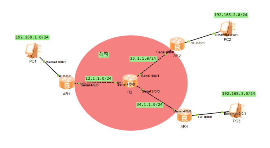
实验
实验要求
- R2为ISP,其上只能配置IP地址
- R1-R2之间为
HDLC封装
- R2-R3之间为
ppp封装,pap认证,R2为主认证方
- R2-R4之间为
ppp封装,chap认证,R2为主认证方
- R1、R3、R4构建
MGRE环境,仅R1 IP地址固定
- 内网使用
RIP协议获取路由,所有PC可以互相访问,并且可以访问R2的环回
实验拓扑
实验步骤
IP配置
R1
1
2
3
4
5
6
7
8
9
10
11
| <Huawei>system-view
Enter system view, return user view with Ctrl+Z.
[Huawei]sysname R1
[R1]interface g0/0/0
[R1-GigabitEthernet0/0/0]ip address 192.168.1.1 24
Jul 18 2022 15:37:17-08:00 R1 %%01IFNET/4/LINK_STATE(l)[0]:The line protocol IP on the interface GigabitEthernet0/0/0 has entered the UP state.
[R1-GigabitEthernet0/0/0]q
[R1]interface s4/0/0
[R1-Serial4/0/0]ip address 12.1.1.1 24
[R1-Serial4/0/0]q
[R1]
|
R2(ISP)
1
2
3
4
5
6
7
8
9
10
11
12
13
14
15
16
17
18
| <Huawei>system-view
Enter system view, return user view with Ctrl+Z.
[Huawei]sysname ISP
[ISP]interface s4/0/0
[ISP-Serial4/0/0]ip address 12.1.1.2 24
[ISP-Serial4/0/0]
Jul 18 2022 15:38:56-08:00 ISP %%01IFNET/4/LINK_STATE(l)[0]:The line protocol PPP IPCP on the interface Serial4/0/0 has entered the UP state.
[ISP-Serial4/0/0]q
[ISP]interface s4/0/1
[ISP-Serial4/0/1]ip address 23.1.1.2 24
[ISP-Serial4/0/1]q
[ISP]interface s3/0/0
[ISP-Serial3/0/0]ip address 34.1.1.2 24
[ISP-Serial3/0/0]q
[ISP]interface LoopBack 0
[ISP-LoopBack0]ip address 2.2.2.2 24
[ISP-LoopBack0]q
[ISP]
|
R3
1
2
3
4
5
6
7
8
9
10
11
12
13
| <Huawei>system-view
Enter system view, return user view with Ctrl+Z.
[Huawei]sysname R3
[R3]interface g0/0/0
[R3-GigabitEthernet0/0/0]ip address 192.168.2.1 24
Jul 18 2022 15:41:34-08:00 R3 %%01IFNET/4/LINK_STATE(l)[0]:The line protocol IP on the interface GigabitEthernet0/0/0 has entered the UP state.
[R3-GigabitEthernet0/0/0]q
[R3]interface s4/0/0
[R3-Serial4/0/0]ip address 23.1.1.3 24
[R3-Serial4/0/0]
Jul 18 2022 15:41:50-08:00 R3 %%01IFNET/4/LINK_STATE(l)[1]:The line protocol PPP IPCP on the interface Serial4/0/0 has entered the UP state.
[R3-Serial4/0/0]q
[R3]
|
R4
1
2
3
4
5
6
7
8
9
10
11
| <Huawei>system-view
Enter system view, return user view with Ctrl+Z.
[Huawei]sysname R4
[R4]interface g0/0/0
[R4-GigabitEthernet0/0/0]ip address 192.168.3.1 24
[R4-GigabitEthernet0/0/0]q
[R4]interface g0/0/0
[R4-GigabitEthernet0/0/0]ip address 34.1.1.4 24
Jul 18 2022 15:42:57-08:00 R4 %%01IFNET/4/LINK_STATE(l)[0]:The line protocol IP on the interface GigabitEthernet0/0/0 has entered the UP state.
[R4-GigabitEthernet0/0/0]q
[R4]
|
HDLC封装(R1-R2)
1
2
3
4
5
6
7
8
9
10
|
[R1]interface s4/0/0
[R1-Serial4/0/0]link-protocol hdlc
Warning: The encapsulation protocol of the link will be changed. Continue? [Y/N]:y
Jul 18 2022 15:46:38-08:00 R1 %%01IFNET/4/CHANGE_ENCAP(l)[0]:The user performed the configuration that will change the encapsulation protocol of the link and then selected Y.
//R2(ISP)
[ISP]interface s4/0/0
[ISP-Serial4/0/0]link-protocol hdlc
Warning: The encapsulation protocol of the link will be changed. Continue? [Y/N]:y
Jul 18 2022 15:47:08-08:00 ISP %%01IFNET/4/CHANGE_ENCAP(l)[0]:The user performed the configuration that will change the encapsulation protocol of the link and then selected Y.
|
ppp封装,pap认证(R2-R3)
1
2
3
4
5
6
7
8
9
10
11
12
13
|
[ISP]aaa
[ISP-aaa]local-user huawei password cipher huawei123
Info: Add a new user.
[ISP-aaa]local-user huawei service-type ppp
[ISP-aaa]q
[ISP]interface s4/0/1
[ISP-Serial4/0/1]link-protocol ppp
[ISP-Serial4/0/1]ppp authentication-mode pap
//R3,被认证方
[R3]interface s4/0/0
[R3-Serial4/0/0]link-protocol ppp
[R3-Serial4/0/0]ppp pap local-user huawei password cipher huawei123
|
ppp封装,chap认证(R2-R4)
1
2
3
4
5
6
7
8
9
10
11
12
13
|
[ISP]aaa
[ISP-aaa]local-user huawei password cipher huawei123
[ISP-aaa]local-user huawei service-type ppp
[ISP-aaa]q
[ISP]interface s3/0/0
[ISP-Serial3/0/0]link-protocol ppp
[ISP-Serial3/0/0]ppp authentication-mode chap
//R4,被认证方
[R4]interface s4/0/0
[R4-Serial4/0/0]link-protocol ppp
[R4-Serial4/0/0]ppp chap user huawei
[R4-Serial4/0/0]ppp chap password cipher huawei123
|
MGRE环境
R1、R3、R4向ISP写缺省路由
1
2
3
4
5
6
|
[R1]ip route-static 0.0.0.0 0 12.1.1.2
[R3]ip route-static 0.0.0.0 0 23.1.1.2
[R4]ip route-static 0.0.0.0 0 34.1.1.2
|
1
2
3
4
5
6
7
8
9
10
11
12
13
14
15
16
17
18
19
20
21
22
23
24
|
[R1]interface Tunnel 0/0/0
[R1-Tunnel0/0/0]ip address 10.1.1.1 24
[R1-Tunnel0/0/0]tunnel-protocol gre p2mp
[R1-Tunnel0/0/0]source 12.1.1.1
Jul 18 2022 16:05:57-08:00 R1 %%01IFNET/4/LINK_STATE(l)[0]:The line protocol IP on the interface Tunnel0/0/0 has entered the UP state.
[R1-Tunnel0/0/0]nhrp entry multicast dynamic
[R1-Tunnel0/0/0]nhrp network-id 100
//R3
[R3]interface Tunnel 0/0/0
[R3-Tunnel0/0/0]ip address 10.1.1.3 24
[R3-Tunnel0/0/0]tunnel-protocol gre p2mp
[R3-Tunnel0/0/0]source s4/0/0
Jul 18 2022 16:21:31-08:00 R3 %%01IFNET/4/LINK_STATE(l)[0]:The line protocol IP on the interface Tunnel0/0/0 has entered the UP state.
[R3-Tunnel0/0/0]nhrp network-id 100
[R3-Tunnel0/0/0]nhrp entry 10.1.1.1 12.1.1.1 register
//R4
[R4]interface Tunnel 0/0/0
[R4-Tunnel0/0/0]ip address 10.1.1.4 24
[R4-Tunnel0/0/0]tunnel-protocol gre p2mp
[R4-Tunnel0/0/0]source s4/0/0
Jul 18 2022 18:06:19-08:00 R4 %%01IFNET/4/LINK_STATE(l)[3]:The line protocol IP on the interface Tunnel0/0/0 has entered the UP state.
[R4-Tunnel0/0/0]nhrp network-id 100
[R4-Tunnel0/0/0]nhrp entry 10.1.1.1 12.1.1.1 register
|
RIP宣告,NAT地址转换
RIP宣告
1
2
3
4
5
6
7
8
9
10
11
12
13
14
15
16
17
18
|
[R1]rip 1
[R1-rip-1]version 2
[R1-rip-1]network 192.168.1.0
[R1-rip-1]network 10.0.0.0
[R1-rip-1]q
[R1]interface Tunnel 0/0/0
[R1-Tunnel0/0/0]undo rip split-horizon
//R3
[R3]rip 1
[R3-rip-1]version 2
[R3-rip-1]network 192.168.2.0
[R3-rip-1]network 10.0.0.0
//R4
[R4]rip 1
[R4-rip-1]version 2
[R4-rip-1]network 192.168.3.0
[R4-rip-1]network 10.0.0.0
|
NAT 地址转换
1
2
3
4
5
6
7
8
9
10
11
12
13
14
15
16
17
18
|
[R1]acl 2000
[R1-acl-basic-2000]rule 1 permit source any
[R1-acl-basic-2000]q
[R1]interface s4/0/0
[R1-Serial4/0/0]nat outbound 2000
//R3
[R3]acl 2000
[R3-acl-basic-2000]rule 1 permit source any
[R3-acl-basic-2000]q
[R3]interface s4/0/0
[R3-Serial4/0/0]nat outbound 2000
//R4
[R4]acl 2000
[R4-acl-basic-2000]rule 1 permit source any
[R4-acl-basic-2000]q
[R4]interface s4/0/0
[R4-Serial4/0/0]nat outbound 2000
|
连通性测试
PC2 -> PC3