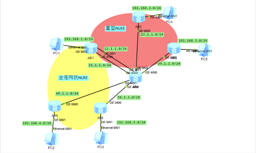
实验要求及拓扑
- R4为ISP,所连接的所有物理接口为共有网段
- R1-2-3 构建一个星型结构MGRE,其中R1为中心站点
- R1-5-6 构建一个全连网状MGRE,其中R1/5均为中心站点
- 使用OSPF实现整个私有网络的互通,同时所有PC可以正常访问R4的环回

实验过程
IP配置
以R4(ISP)为例
1
2
3
4
5
6
7
8
9
10
11
12
13
14
15
16
17
18
19
20
| [ISP]interface LoopBack 0
[ISP-LoopBack0]ip address 4.4.4.4 24 //公网IP
[ISP-LoopBack0]quit
[ISP]interface g0/0/0
[ISP-GigabitEthernet0/0/0]ip address 21.1.1.4 24
[ISP-GigabitEthernet0/0/0]quit
[ISP]interface g0/0/1
[ISP-GigabitEthernet0/0/1]ip address 12.1.1.4 24
[ISP-GigabitEthernet0/0/1]quit
[ISP]interface g0/0/2
[ISP-GigabitEthernet0/0/2]ip address 23.1.1.4 24
[ISP-GigabitEthernet0/0/2]quit
[ISP]interface g4/0/0
[ISP-GigabitEthernet4/0/0]ip address 34.1.1.4 24
[ISP-GigabitEthernet4/0/0]quit
[ISP]interface g4/0/1
[ISP-GigabitEthernet4/0/1]ip address 45.1.1.4 24
[ISP-GigabitEthernet4/0/1]quit
[ISP]interface g4/0/2
[ISP-GigabitEthernet4/0/2]ip address 56.1.1.4 24
|
星型MGRE
先配置R1-6指向ISP的缺省(不做展示)
1
2
3
4
5
6
7
8
9
10
11
12
13
14
15
16
17
18
19
20
21
22
23
24
|
[R1]interface Tunnel 0/0/0
[R1-Tunnel0/0/0]ip address 10.1.1.1 24
[R1-Tunnel0/0/0]tunnel-protocol gre p2mp
[R1-Tunnel0/0/0]source 12.1.1.1
Jul 22 2022 18:55:09-08:00 R1 %%01IFNET/4/LINK_STATE(l)[0]:The line protocol IP on the interface Tunnel0/0/0 has entered the UP state.
[R1-Tunnel0/0/0]nhrp entry multicast dynamic
[R1-Tunnel0/0/0]nhrp network-id 100
//R2
[R2]interface Tunnel 0/0/0
[R2-Tunnel0/0/0]ip address 10.1.1.2 24
[R2-Tunnel0/0/0]tunnel-protocol gre p2mp
[R2-Tunnel0/0/0]source g0/0/0
Jul 22 2022 18:57:24-08:00 R2 %%01IFNET/4/LINK_STATE(l)[0]:The line protocol IP on the interface Tunnel0/0/0 has entered the UP state.
[R2-Tunnel0/0/0]nhrp network-id 100
[R2-Tunnel0/0/0]nhrp entry 10.1.1.1 12.1.1.1 register
//R3
[R3]interface Tunnel 0/0/0
[R3-Tunnel0/0/0]ip address 10.1.1.3 24
[R3-Tunnel0/0/0]tunnel-protocol gre p2mp
[R3-Tunnel0/0/0]source g0/0/0
Jul 22 2022 18:58:59-08:00 R3 %%01IFNET/4/LINK_STATE(l)[0]:The line protocol IP on the interface Tunnel0/0/0 has entered the UP state.
[R3-Tunnel0/0/0]nhrp network-id 100
[R3-Tunnel0/0/0]nhrp entry 10.1.1.1 12.1.1.1 register
|
全连网状MGRE
1
2
3
4
5
6
7
8
9
10
11
12
13
14
15
16
17
18
19
20
21
22
23
24
25
26
|
[R1]interface Tunnel 0/0/1
[R1-Tunnel0/0/1]ip address 20.1.1.1 24
[R1-Tunnel0/0/1]tunnel-protocol gre p2mp
[R1-Tunnel0/0/1]source 21.1.1.1
Jul 22 2022 19:06:32-08:00 R1 %%01IFNET/4/LINK_STATE(l)[0]:The line protocol IP on the interface Tunnel0/0/1 has entered the UP state.
[R1-Tunnel0/0/1]nhrp entry multicast dynamic
[R1-Tunnel0/0/1]nhrp network-id 200
//R5(中心站点)
[R5]interface Tunnel 0/0/1
[R5-Tunnel0/0/1]ip address 20.1.1.5 24
[R5-Tunnel0/0/1]tunnel-protocol gre p2mp
[R5-Tunnel0/0/1]source 45.1.1.5
Jul 22 2022 19:08:26-08:00 R5 %%01IFNET/4/LINK_STATE(l)[0]:The line protocol IP on the interface Tunnel0/0/1 has entered the UP state.
[R5-Tunnel0/0/1]nhrp entry multicast dynamic
[R5-Tunnel0/0/1]nhrp network-id 200
[R5-Tunnel0/0/1]nhrp entry 20.1.1.1 21.1.1.1 register
//R6
[R6]interface Tunnel 0/0/1
[R6-Tunnel0/0/1]ip address 20.1.1.6 24
[R6-Tunnel0/0/1]tunnel-protocol gre p2mp
[R6-Tunnel0/0/1]source 56.1.1.6
Jul 22 2022 19:10:02-08:00 R6 %%01IFNET/4/LINK_STATE(l)[0]:The line protocol IP on the interface Tunnel0/0/1 has entered the UP state.
[R6-Tunnel0/0/1]nhrp network-id 200
[R6-Tunnel0/0/1]nhrp entry 20.1.1.1 21.1.1.1 register
[R6-Tunnel0/0/1]nhrp entry 20.1.1.5 45.1.1.5 register
|
OSPF
1
2
3
4
5
6
7
8
9
10
11
12
13
14
15
16
17
18
19
20
21
22
23
24
25
26
27
28
29
30
|
[R1]ospf 1 router-id 1.1.1.1
[R1-ospf-1]area 0
[R1-ospf-1-area-0.0.0.0]network 192.168.1.1 0.0.0.0
[R1-ospf-1-area-0.0.0.0]network 10.1.1.1 0.0.0.0
[R1-ospf-1-area-0.0.0.0]quit
[R1-ospf-1]area 1
[R1-ospf-1-area-0.0.0.1]network 20.1.1.1 0.0.0.0
[R2]ospf 1 router-id 2.2.2.2
[R2-ospf-1]area 0
[R2-ospf-1-area-0.0.0.0]network 192.168.2.1 0.0.0.0
[R2-ospf-1-area-0.0.0.0]network 10.1.1.2 0.0.0.0
[R3]ospf 1 router-id 3.3.3.3
[R3-ospf-1]area 0
[R3-ospf-1-area-0.0.0.0]network 192.168.3.1 0.0.0.0
[R3-ospf-1-area-0.0.0.0]network 10.1.1.3 0.0.0.0
[R5]ospf 1 router-id 5.5.5.5
[R5-ospf-1]area 1
[R5-ospf-1-area-0.0.0.1]network 192.168.4.1 0.0.0.0
[R5-ospf-1-area-0.0.0.1]network 20.1.1.5 0.0.0.0
[R6]ospf 1 router-id 6.6.6.6
[R6-ospf-1]area 1
[R6-ospf-1-area-0.0.0.1]ne
[R6-ospf-1-area-0.0.0.1]network 192.168.5.1 0.0.0.0
[R6-ospf-1-area-0.0.0.1]ne
[R6-ospf-1-area-0.0.0.1]network 20.1.1.6 0.0.0.0
|
在NBMA网络中,接口类型为p2p,故OSPF协议不能正常建立邻居关系,此时要将其所有接口均修改为Broadcast;
R2和R3在星型MGRE网络中,还要使其放弃DR选举,否则area 0选路将不一致
1
2
3
4
5
6
7
8
9
10
11
12
13
14
15
16
17
18
19
20
|
[R1]interface Tunnel 0/0/0
[R1-Tunnel0/0/0]ospf network-type broadcast
[R1-Tunnel0/0/0]quit
[R1]interface Tunnel 0/0/1
[R1-Tunnel0/0/1]ospf network-type broadcast
//R2
[R2]interface Tunnel 0/0/0
[R2-Tunnel0/0/0]ospf network-type broadcast
[R2-Tunnel0/0/0]ospf dr-priority 0
//R3
[R3]interface Tunnel 0/0/0
[R3-Tunnel0/0/0]ospf network-type broadcast
[R3-Tunnel0/0/0]ospf dr-priority 0
//R5
[R5]interface Tunnel 0/0/1
[R5-Tunnel0/0/1]ospf network-type broadcast
//R6
[R6]interface Tunnel 0/0/1
[R6-Tunnel0/0/1]ospf network-type broadcast
|
NAT地址转换,以R1为例
1
2
3
4
5
| [R1]acl 2000
[R1-acl-basic-2000]rule 1 permit source any
[R1-acl-basic-2000]q
[R1]int g0/0/1
[R1-GigabitEthernet0/0/1]nat outbound 2000
|
路由表展示及连通性测试